Flowchart
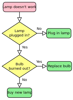
A flowchart is a common type of chart that represents an algorithm or process, showing the steps as boxes of various kinds and the order of steps by arrows that connect the boxes. It may also contain other symbols, such as circles, to represent converging paths in the chart.
Flowcharts are used in designing or documenting processes or programs in various fields. They help the viewer understand and get an overview of the process, also providing the opportunity to detect flaws and to come up with better ways of carrying out the process.
Overview
The two most common types of boxes in a flowchart are:
- a processing step (usually called activity, and denoted as a rectangular box)
- a decision (usually denoted as a diamond)
There are many different types of flowchart, and each type has its own repertoire of boxes and notational conventions.
A flowchart is described as "cross-functional" when the page is divided into different swimlanes describing the control of different organizational units. A symbol appearing in a particular "lane" is within the control of that organizational unit. This technique allows the author to locate the responsibility for performing an action or making a decision correctly, showing the responsibility of each organizational unit for different parts of a single process.
Flowcharts are used in designing and documenting complex processes.[1] Like other types of diagram, they help visualize what is going on and thereby help the viewer to understand a process, and perhaps also find flaws, bottlenecks, and other less-obvious features within it.
Flowcharts depict certain aspects of processes and they are usually complemented by other types of diagram. For instance, Kaoru Ishikawa defined the flowchart as one of the seven basic tools of quality control, next to the histogram, Pareto chart, check sheet, control chart, cause-and-effect diagram, and the scatter diagram.[2] Likewise, in Unified Modeling Language (UML), a standard concept-modeling notation used in software development, the activity diagram, which is a type of flowchart, is just one of many different diagram types.
Nassi-Shneiderman diagrams are an alternative notation for process flow.
History
The first structured method for documenting process flow, the "flow process chart," was introduced by Frank Gilbreth to members of American Society of Mechanical Engineers (ASME) in 1921 as the presentation “Process Charts—First Steps in Finding the One Best Way.” Gilbreth's tools quickly found their way into industrial engineering curricula. In the early 1930s, an industrial engineer, Allan H. Mogensen began training business people in the use of some of the tools of industrial engineering at his Work Simplification Conferences in Lake Placid, New York.
A 1944 graduate of Mogensen's class, Art Spinanger, took the tools back to Procter and Gamble where he developed their Deliberate Methods Change Program. Another 1944 graduate, Ben S. Graham, Director of Formcraft Engineering at Standard Register Corporation, adapted the flow process chart to information processing with his development of the multi-flow process chart to display multiple documents and their relationships. In 1947, ASME adopted a symbol set derived from Gilbreth's original work as the ASME Standard for Process Charts.
According to Herman Goldstine, he developed flowcharts with John von Neumann at Princeton University in late 1946 and early 1947.[3]
Flowcharts used to be a popular means for describing computer algorithms, and they are still used for this purpose. Modern techniques such as Unified Modeling Language (UML) activity diagrams can be considered extensions of the flowchart. However, their popularity decreased when, in the 1970s, interactive computer terminals and third-generation programming languages became the common tools of the trade, since algorithms can be expressed much more concisely and readably as source code in such a language. Often, pseudo-code is used, which uses the common idioms of such languages without strictly adhering to the details of a particular one.
Flow chart building blocks
Symbols
A typical flowchart from older Computer Science textbooks may have the following kinds of symbols:
- Start and end symbols
- Represented as lozenges, ovals or rounded rectangles, usually containing the word "Start" or "End," or another phrase signaling the start or end of a process, such as "submit enquiry" or "receive product."
- Arrows
- Showing what's called "flow of control" in computer science. An arrow coming from one symbol and ending at another symbol represents that control passes to the symbol the arrow points to.
- Processing steps
- Represented as rectangles. Examples: "Add 1 to X"; "replace identified part"; "save changes" or similar.
- Input/Output
- Represented as a parallelogram. Examples: Get X from the user; display X.
- Conditional or decision
- Represented as a diamond (rhombus). These typically contain a Yes/No question or True/False test. This symbol is unique in that it has two arrows coming out of it, usually from the bottom point and right point, one corresponding to Yes or True, and one corresponding to No or False. The arrows should always be labeled. More than two arrows can be used, but this is normally a clear indicator that a complex decision is being taken, in which case it may need to be broken-down further, or replaced with the "pre-defined process" symbol.
A number of other symbols that have less universal currency, such as:
- A Document represented as a rectangle with a wavy base;
- A Manual input represented by parallelogram, with the top irregularly sloping up from left to right. An example would be to signify data-entry from a form;
- A Manual operation represented by a trapezoid with the longest parallel side at the top, to represent an operation or adjustment to process that can only be made manually;
- A Data File represented by a cylinder.
Flowcharts may contain other symbols, such as connectors, usually represented as circles, to represent converging paths in the flow chart. Circles will have more than one arrow coming into them but only one going out. Some flow charts may just have an arrow point to another arrow instead. These are useful to represent an iterative process (what in Computer Science is called a loop). A loop may, for example, consist of a connector where control first enters, processing steps, a conditional with one arrow exiting the loop, and one going back to the connector. Off-page connectors are often used to signify a connection to a (part of another) process held on another sheet or screen. It is important to remember to keep these connections logical in order. All processes should flow from top to bottom and left to right.
Examples
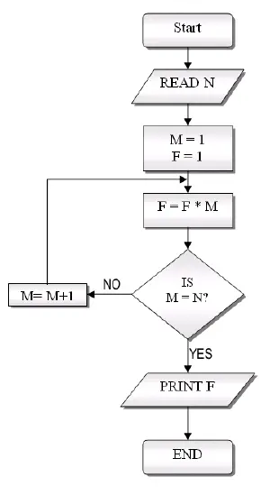
A flowchart for computing factorial N (N!) Where N! = 1 * 2 * 3 *...* N. This flowchart represents a "loop and a half"—a situation discussed in introductory programming textbooks that requires either a duplication of a component (to be both inside and outside the loop) or the component to be put inside a branch in the loop.
Software
Manual
Any vector-based drawing program can be used to create flowchart diagrams, but these will have no underlying data model to share data with databases or other programs such as project management systems or spreadsheets. Some tools offer special support for flowchart drawing, e.g., ConceptDraw, SmartDraw, EDraw Flowchart, Visio, and OmniGraffle.
Automatic
Many software packages exist that can create flowcharts automatically, either directly from source code, or from a flowchart description language. For example, Graph::Easy, a Perl package, takes a textual description of the graph, and uses the description to generate various output formats including HTML, ASCII or SVG.
See also
- Graph
- Activity diagram
- Augmented transition network
- Business process illustration
- Business Process Mapping
- Control flow graph
- Data flow diagram
- Flow map
- Functional flow block diagram
- N2 Chart
- Petri nets
- Process architecture
- Pseudocode
- Recursive transition network
- Sankey diagram
- State diagram
Notes
- ↑ SEVOCAB: Software and Systems Engineering Vocabulary IEEE Computer Society. Retrieved December 16, 2008.
- ↑ Matthew Moore (30 Nov 2007), The seven basic tools of quality.
- ↑ Herman Heine Goldstine, The Computer from Pascal to Von Neumann (Princeton, NJ: Princeton University Press, 1972, ISBN 0691081042).
ReferencesISBN links support NWE through referral fees
- Damelio, Robert. The Basics of Process Mapping. Productivity Press, 1996. ISBN 0527763160
- Harrington, H.J., E. K. C. Esseling, and H. van Nimwegen. Business Process Improvement Workbook: Documentation, Analysis, Design, and Management of Business Process Improvement. New York: McGraw-Hill, 1997. ISBN 978-0070267794
- Joiner Associates Staff. Flowcharts: Plain & Simple. Learning and Application Guide. Madison, WI: Oriel Inc, 2002 (original 1995). ISBN 1884731031
- Madison, Dan. Process Mapping, Process Improvement, and Process Management: A Practical Guide for Enhancing Work and Information Flow. Chico, CA: Paton Press, 2005. ISBN 978-1932828047
External links
All links retrieved April 14, 2017.
- Information processing—Documentation symbols and conventions for data, program and system flowcharts, program network charts and system resources charts International Organization for Standardization.
- Flowcharting Techniques IBM Data Processing Techniques. (IBM manual from 1969, 5MB PDF format).
- Advanced Flowchart Tipskey. (Why and how to create an advanced flowchart.)
Credits
New World Encyclopedia writers and editors rewrote and completed the Wikipedia article in accordance with New World Encyclopedia standards. This article abides by terms of the Creative Commons CC-by-sa 3.0 License (CC-by-sa), which may be used and disseminated with proper attribution. Credit is due under the terms of this license that can reference both the New World Encyclopedia contributors and the selfless volunteer contributors of the Wikimedia Foundation. To cite this article click here for a list of acceptable citing formats.The history of earlier contributions by wikipedians is accessible to researchers here:
The history of this article since it was imported to New World Encyclopedia:
Note: Some restrictions may apply to use of individual images which are separately licensed.

