Gyroscope
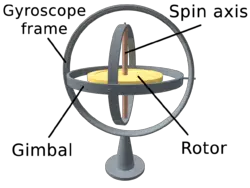
A gyroscope is a device for measuring or maintaining orientation, based on the principle of conservation of angular momentum. The key component, a relatively heavy spinning rotor, is mounted with nearly frictionless bearings inside two concentric lightweight rings (gimbals) each of which is also mounted with similar bearings inside the next outer ring, or the support frame in the case of the outer ring.
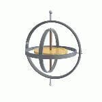
The rotor and the two rings are mounted so the plane of rotation for each is perpendicular to the plane of rotation of the other two. The spinning rotor naturally resists changes to its orientation due to the angular momentum of the wheel. In physics, this phenomenon is also known as gyroscopic inertia or rigidity in space. Thanks to its unique support in the nested gimbals the rotor is able to hold a nearly constant orientation even as the support frame shifts its orientation.
The gyroscope's ability to hold its axis fixed in a certain orientation, or in some applications to precess about an axis, even as its supporting structure is moved into different positions has permitted it to be used in making vast improvements to navigational systems and precision instruments.
Description and diagram
A conventional gyroscope comprises two concentric rings or gimbals plus a central rotor mounted in bearings on the inside of the inner gimbal, which in turn is mounted in bearings set in the outer gimbal, which is also supported with bearings set into a support frame. The rotor, the inner gimbal, and the outer gimbal then can each move freely in its own plane determined by its level of support. The inner gimbal is mounted in the outer gimbal in such a way that the inner gimbal pivots about an axis in its own plane that is always perpendicular to the pivotal axis of the outer gimbal. Similarly, the bearings of the rotor's axis are mounted in the inner gimbal in a position to assure that the rotor's spin axis is always perpendicular to the axis of the inner gimbal.
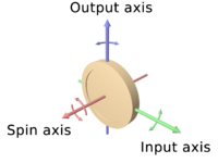
The rotor wheel responds to a force applied about the input axis (connected with the inner gimbal) by a reaction force about the output axis (connected with the outer gimbal). The 3 axes are perpendicular, and this cross-axis response is the simple essence of the gyroscopic effect.
A gyroscope flywheel will roll or resist about the output axis depending upon whether the output gimbals are of a free or fixed configuration. Examples of some free-output-gimbal devices would be the attitude reference gyroscopes used to sense or measure the pitch, roll, and yaw attitude angles in a spacecraft or aircraft.
The center of gravity of the rotor can be in a fixed position. The rotor simultaneously spins about one axis and is capable of oscillating about the two other axes, and thus, except for its inherent resistance due to rotor spin, it is free to turn in any direction about the fixed point. Some gyroscopes have mechanical equivalents substituted for one or more of the elements. For example, the spinning rotor may be suspended in a fluid, instead of being pivotally mounted in gimbals. A control moment gyroscope (CMG) is an example of a fixed-output-gimbal device that is used on spacecraft to hold or maintain a desired attitude angle or pointing direction using the gyroscopic resistance force.
In some special cases, the outer gimbal (or its equivalent) may be omitted so that the rotor has only two degrees of freedom. In other cases, the center of gravity of the rotor may be offset from the axis of oscillation, and thus the center of gravity of the rotor and the center of suspension of the rotor may not coincide.
History
The gyroscope effect was discovered in 1817 by Johann Bohnenberger; the gyroscope was invented, and the effect named after it, in 1852 by Léon Foucault for an experiment involving the rotation of the Earth. Foucault's experiment to see (skopeein, to see) the Earth's rotation (gyros, circle or rotation) was unsuccessful due to friction, which effectively limited each trial to 8 to 10 minutes, too short a time to observe significant movement. In the 1860s, however, electric motors made the concept feasible, leading to the first prototype gyrocompasses; the first functional marine gyrocompass was developed between 1905 and 1908 by German inventor Hermann Anschütz-Kaempfe. The American Elmer Sperry followed with his own design in 1910, and other nations soon realized the military importance of the invention—in an age in which naval might was the most significant measure of military power—and created their own gyroscope industries. The Sperry Gyroscope Company quickly expanded to provide aircraft and naval stabilizers as well, and other gyroscope developers followed suit.[1]
In the first several decades of the twentieth century, other inventors attempted (unsuccessfully) to use gyroscopes as the basis for early black box navigational systems by creating a stable platform from which accurate acceleration measurements could be performed (in order to bypass the need for star sightings to calculate position). Similar principles were later employed in the development of inertial guidance systems for ballistic missiles.[2]
Properties
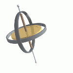
A gyroscope exhibits a number of types of behavior, including precession and nutation. Gyroscopes can be used to construct gyrocompasses which complement or replace magnetic compasses (in ships, aircraft, spacecraft, and vehicles in general), to assist in stability (bicycle, Hubble Space Telescope, ships, vehicles in general) or be used as part of an Inertial guidance system. Gyroscopic effects are used in toys like yo-yos and Powerballs. Many other rotating devices, such as flywheels, behave gyroscopically although the gyroscopic effect is not used.
The fundamental equation describing the behavior of the gyroscope is:
where the vectors and are, respectively, the torque on the gyroscope and its angular momentum, the scalar is its moment of inertia, the vector is its angular velocity, and the vector is its angular acceleration.
It follows from this that a torque applied perpendicular to the axis of rotation, and therefore perpendicular to , results in a motion perpendicular to both and . This motion is called "precession." The angular velocity of precession is given by the cross product:
Precession can be demonstrated by placing a spinning gyroscope with its axis horizontal and supported loosely (frictionless toward precession) at one end. Instead of falling, as might be expected, the gyroscope appears to defy gravity by remaining with its axis horizontal, when the other end of the axis is left unsupported and the free end of the axis slowly describes a circle in a horizontal plane, the resulting precession turning. This effect is explained by the above equations. The torque on the gyroscope is supplied by a couple of forces: Gravity acting downwards on the device's center of mass, and an equal force acting upwards to support one end of the device. The motion resulting from this torque is not downwards, as might be intuitively expected, causing the device to fall, but perpendicular to both the gravitational torque (downwards) and the axis of rotation (outwards from the point of support), that is in a forward horizontal direction, causing the device to rotate slowly about the supporting point.
As the second equation shows, under a constant torque due to gravity or not, the gyroscope's speed of precession is inversely proportional to its angular momentum. This means that, for instance, if friction causes the gyroscope's spin to slow down, the rate of precession increases. This continues until the device is unable to rotate fast enough to support its own weight, when it stops precessing and falls off its support, mostly because friction against precession cause another precession that goes to cause the fall.
By convention, these three vectors, torque, spin, and precession, are all oriented with respect to each other according to the right-hand rule.
To easily ascertain the direction of gyro effect, simply remember that a rolling wheel tends, when entering a corner, to turn over to the inside.
Gyrostat
A gyrostat is a variant of the gyroscope. The first gyrostat was designed by Lord Kelvin to illustrate the more complicated state of motion of a spinning body when free to wander about on a horizontal plane, like a top spun on the pavement, or a hoop or bicycle on the road. It consists essentially of a massive flywheel concealed in a solid casing. Its behavior on a table, or with various modes of suspension or support, serves to illustrate the curious reversal of the ordinary laws of static equilibrium due to the gyrostatic behavior of the interior invisible flywheel when rotated rapidly.
Small, manually spun gyrostats are sold as children's toys.
Fiber optic gyroscope
A fiber optic gyroscope (FOG) is a device that uses the interference of light to detect mechanical rotation. The sensor is a coil of as much as 5 kilometers (km) of optical fiber. Two light beams travel along the fiber in opposite directions. Due to the Sagnac effect, the beam traveling against the rotation experiences a slightly shorter path than the other beam. The resulting phase shift affects how the beams interfere with each other when they are combined. The intensity of the combined beam then depends on the rotation rate of the device.
A FOG provides extremely precise rotational rate information, in part because of its lack of cross-axis sensitivity to vibration, acceleration, and shock. Unlike the classic spinning-mass gyroscope, the FOG has virtually no moving parts and no inertial resistance to movement. The FOG typically shows a higher resolution than a ring laser gyroscope but also a higher drift and worse scale factor performance. It is used in surveying, stabilization, and inertial navigation tasks.
FOGs are designed in both open-loop and closed-loop configurations.
Ring laser gyroscope
A ring laser gyroscope uses interference of laser light within a bulk optic ring to detect changes in orientation and spin. It is an application of a Sagnac interferometer.
Ring laser gyros (RLG) can be used as the stable elements (for one degree of freedom each) in an inertial reference system. The advantage of using a RLG is that there are no moving parts. Compared to the conventional spinning gyro, this means there is no friction, which in turn means there will be no inherent drift terms. Additionally, the entire unit is compact, lightweight, and virtually indestructible, meaning it can be used in aircraft. Unlike a mechanical gyroscope, the device does not resist changes to its orientation.
Physically, an RLG is composed of segments of transmission paths configured as either a square or a triangle and connected with mirrors. One of the mirrors will be partially silvered, allowing light through to the detectors. A laser beam is launched into the transmission path in both directions, establishing a standing wave resonant with the length of the path. As the apparatus rotates, light in one branch travels a different distance than the other branch, changing its phase and resonant frequency with respect to the light traveling in the other direction, resulting in the interference pattern beating at the detector. The angular position is measured by counting the interference fringes.
RLGs, while more accurate than mechanical gyros, suffer from an effect known as "lock-in" at very slow rotation rates. When the ring laser is rotating very slowly, the frequencies of the counter-rotating lasers become very close (within the laser bandwidth). At this low rotation, the nulls in the standing wave tend to "get stuck" on the mirrors, locking the frequency of each beam to the same value, and the interference fringes no longer move relative to the detector; in this scenario, the device will not accurately track its angular position over time.
Dithering can compensate for lock-in. The entire apparatus is twisted and untwisted about its axis at a rate convenient to the mechanical resonance of the system, thus ensuring that the angular velocity of the system is usually far from the lock-in threshold. Typical rates are 400Hz, with a peak dither velocity of 1 arc-second per second.
Primary applications include navigation systems on commercial airliners, ships, and spacecraft, where RLGs are often referred to as Inertial Reference Systems. In these applications, it has replaced its mechanical counterpart, the Inertial guidance system.
Examples of aerospace vehicles or weapons that use RLG systems:
- Trident missile (D5 Trident II)
- F-15E Strike Eagle
Notes
- ↑ MacKenzie, Donald. Inventing Accuracy: A Historical Sociology of Nuclear Missile Guidance (Cambridge, MA: MIT Press, 1990). pp 31-40. ISBN 0-262-13258-3
- ↑ MacKenzie, pp 40-42.
ReferencesISBN links support NWE through referral fees
- LeFèvre, Hervé C. The Fiber-Optic Gyroscope. Norwood, MA: Artech House, 1993. ISBN 0890065373
- Machover, Carl. Basics of Gyroscopes Vol. 1. New York, NY: John F. Rider Publishing, 1963.
- Walton, Harry. The How and Why of Mechanical Movements - Exactly How Machines Work: Engines, Turbines, Transmissions, Brakes, Clutches, Rockets, Atomic Generators, Gyroscopes, Guidance Systems. Tampa, FL: Popular Science, 1968.
External links
All links retrieved July 22, 2017.
- The Precession and Nutation of a Gyroscope
- Everything you needed to know about gyroscopes
- Videos of gyroscopes working
Credits
New World Encyclopedia writers and editors rewrote and completed the Wikipedia article in accordance with New World Encyclopedia standards. This article abides by terms of the Creative Commons CC-by-sa 3.0 License (CC-by-sa), which may be used and disseminated with proper attribution. Credit is due under the terms of this license that can reference both the New World Encyclopedia contributors and the selfless volunteer contributors of the Wikimedia Foundation. To cite this article click here for a list of acceptable citing formats.The history of earlier contributions by wikipedians is accessible to researchers here:
The history of this article since it was imported to New World Encyclopedia:
Note: Some restrictions may apply to use of individual images which are separately licensed.


